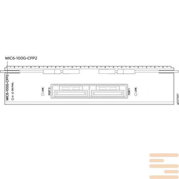
Module Juniper MIC6-100G-CFP2
147420 $
interfacefees or linearcards Juniper Networks (line card, interface module) allow you to expand your router or switch (modular platform, chassis) Required functional, including the necessary access ports at speeds 1GbE, 10GbE, 40GbEor 100GbE, control boards (switch control board) etc..
Interface boards Juniper represented by various modules that are compatible with a particular series (for example. interface module MS-MIC-16G compatible with the entire range Juniper MX, and the module MPC-3D-16XGE-SFPP series compatible MX240, MX480 andMX960).
interface board MIC (Modular Interface Cards) is a small-sized module that provides physical connection to various types of network devices. MIC the board can support various physical interfaces in one module. module Juniper MICs also support hot swapping and plugging. For example, in routers MX series, interface module MIC installed in the module MPC (Modular Port Concentrator), and in series from MX5 before MX104 module MPC already built in chassis.
interface module Juniper MPC (Modular Port Concentrator) provides transfer services Lkand packages. module MPC encapsulates packets and passes them through the module's outgoing interfaces MIC. everyone MPC module equipped with up to four chipsets Junos Trio, which performs the functions of management. For example, a router Juniper MX960 supports installation of up to 12 modules MPCs, and the platform MX480 before 3 MPCs. For proper operation module Juniper MPC You need to use high-performance cooling modules. Online Juniper http://www.juniper.net there is a calculator for calculating the recommended power and cooling power, for a specific series and used MPC modules.
Interface modules DPC (Dense Port Concentrators) Provides several physical interfaces and pass systems Lkand packages on a single board that fits into a slot in a router or modular chassis. module DPC accepts incoming packets and sends outgoing packets to the network.
module Juniper PIC (Physical Interface Card) installed in FPC (Flexible PIC Concentrators), similar to how they work MIC andMPC modules. PICs modules provide physical interfaces, and FPCs boards provide transfers Lkfor packets on the network. everyone FPCthe module is equipped with a microchip ASIC, which performs the functions of management, and FPC supports installation of 2 modules PIC.
Technical characteristics of the interface module JuniperMIC6-100G-CFP2:
|
Software release |
|
|
Description |
|
|
Hardware features |
|
|
Software features |
|
|
Cables and connectors |
Tip: You can use the Hardware Compatibility Tool to find information about the pluggable transceivers supported on your Juniper Networks device. The list of supported transceivers for the MX Series is located at https://pathfinder.juniper.net/hct/category/#catKey=100001&modelType;=All&pf;=MX+Series. Note: CFP2-100G-ER4-D is not NEBS compliant on the MX960 router in FPC slot 0 or FPC slot 11. Note: When inserting the CFP2 transceiver, ensure that the transceiver sits tightly in the port. You will hear a distinct click sound when the latch locks into the corresponding port. The latch must be fully engaged in the corresponding port for the CFP2 transceiver to function properly. Failing to do so will result in loss of connection. To verify that the CFP2 transceiver module is inserted properly, give a gentle pull by grasping the sides of the module. The module should sit tightly. |
|
LEDs |
OK/FAIL LED, one tricolor:
LINK LED, one bicolor per port:
Port labels:
|
| condition | new |
|---|

Log In